Wood Solutions | 9 Hooker Ave | Northampton | 01060 | Tel: 413-588-2984 Web Updated 1/16/2017

In 2004 I decided to build a CNC router for my shop. In the past I`ve built other machines for the shop. Including a combination wide belt
sander | planer and pin router . These machines were built with metalworking tools including a south bend lathe, metal cut-off saw and a drill
press.
Part of the reason for this build was to construct a machine that was capable of machining wood and metal. The end result provided a
machine that capable of milling wood, aluminum and steel.
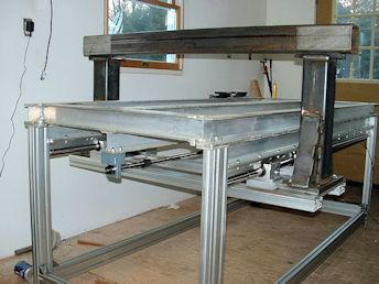
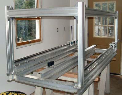
I managed to find a fabricated aluminum frame comprised of tig welded I
beams. This assembly defined the overall size of the machine 36 X 80.
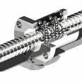
eBay as usual is the place to find used components at a faction of the price for
new precision assemblies. I found ball screw assemblies with the bearing
blocks and purchased three sets. Only the bearing blocks were used for the
machine. The ball screws purchased were XPR inch precision rolled ball screws
from Nook Industries. All were 5/8 diameter by .2 pitch.
This pitch is very common in the DIY world as it provides
an excellent machine resolution.
It should be mentioned that all ball screws have a critical
speed. At a certain speed the ball screw starts to shake.
At a given ball screw diameter the critical speed issues
can be minimized by reducing the maximum ipm of the
machine. In my case, a 67 inch screw length produced extreme shake at 250
ipm. Setting the maximum speed of the machine to 200 ipm resolved the
problem.
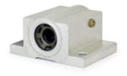
Thomson Ball Bushing BearingI started to mount my Thomson 1 1/4" diameter linear motion rails to the bottom of my frame. This required
48 bolt holes to be drilled in the aluminum frame. I secured one rail and then set up a measuring system to check the
other X axis rail for parallel. I mounted a dial indicator to an aluminum extrusion and linked it to two Thomson blocks. I
adjusted the blocks as tightly as possible to eliminate any clearances. After about 5 hours I managed to position the two X
rails within .002" of parallel.
As a test, I mounted a 15" x 36" piece of MDF to the four sliding blocks and
pushed the new assembly along the full length of the X axis to test for any binding. It seemed fine
but I did push one side and the complete assembly twisted a bit. As a design note: it was
recommended by Thomson Industries that
the spacing of the sliding blocks should be
set to match the width of the machine. To
clarify, my machine is 36" wide, so the
spacing of the blocks should be 36 inches
apart.
If I had followed these guidelines I would have reduced the usable travel of the machine
considerably. So I compromised and set the spacing to 15 inches.
I then went to work designing the gantry. I decided on 4 inch structural tubing with a wall
thickness of 3/16. I had thought about using aluminum extrusions. In my searches I
never found a size close to 4 x 4. Aluminum would have been easier to work and
considerably lighter then the steel. It was my belief that a larger tube would allow me to
space the THK sliding elements farther apart, making a more rigid design. After welding of gantry ends were completed. I sent the gantry
weldments off to a machinist to mill the top and bottom plates. This provided a reliable reference surface to mount the Y axis tube to gantry
uprights. The top tube shown here was also sent to a machine shop which had a large Blanchard grinding machine. All four surfaces of the Y
axis tube were ground. This cost $200 and provided a very flat surface to mount the THK linear rails.
My next step was to mount, 4 THK linear rails and blocks. I planned to butt joint the rails end to end to achieve the needed length. It is
standard practice to use full length rails for CNC construction. I managed to install the butt jointed rails without any problems.
As a design note: it’s a good idea to find engineering information regarding the strength of materials. It’s very
surprising to find structural steel elements will deflect under load more than you might expect. The 4 X 4 tube had
no noticeable defection taking into consideration the amount of weight the
Z axis applied to the Y axis tube.
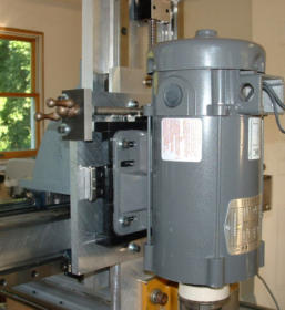
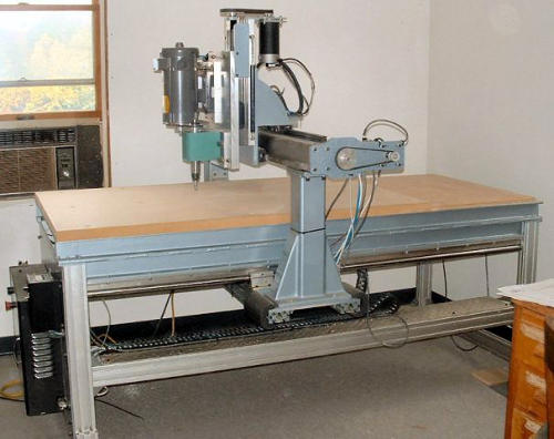
The next step was designing the Z axis assembly. It was my intent to use a
spindle designed for metal instead of the typical wood router. I used a
spindle purchased from the Little Machine Shop. This spindle allowed me
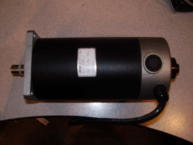
to use R8 collets for all my cutters. I needed to drive the spindle and decided on a Baldor 1 HP DC
motor. This motor system is designed to be controlled by a electronic speed control. This allows
infinite speed control of the spindle. Something I felt I needed if I was going to machine steel.
Since this spindle was belt driven, it required a sliding motor mount to allow tensioning of the
pulleys. The picture below shows a THK wide body slide which is secured to a black painted
aluminum sub-plate. This functions as a sliding motor mount. To manually take up the belt tension a
surplus acme screw was used. I did have a design oversight with this spindle. I originally setup a
large timing pulley on the motor and a smaller pulley on the spindle. This configuration worked fine for my woodworking but failed in my
attempts with steel.
By woodworking standards the spindle speed is considered slow at 4500 rpm. In all my woodworking tests I found this speed worked just
fine. Another added benefit was the very low volume of noise the spindle produced. 4500 rpm was the highest speed that I could run the
spindle for an extended amount of tine 5 hours. Being that the spindle was designed for metalworking and considering the bearing type. It
was not possible to gear the spindle to match the speeds of a wood router. The bearing type and amount of preload on the bearings would
have severely overheated the spindle.
In my attempts with steel I found that the spindle had almost no torque when it was reduced in speed to 800 rpm. This was of course the
result of the original pulley sizing. Taking a 1 HP
motor geared for a maximum speed of 4500 and
running at a lower input speed via the electronic
speed control negated any horsepower to the
spindle. The solution to this problem was to
incorporate a two step pulley system. I purchased a
pulley set from The Little Machine Shop and used
the supplied double step pulley for the spindle. I
then machined an aluminum double step pulley for
the motor that allowed for better torque
transmission at high and low speeds. These extra
steps did resolve my problem.
Here are the results of the spindle modifications.
To the lefy er habe a YouTube video of the
machining of a new cast-iron work surface. A few
years ago I added this cast iron table to the end the machine table. This addition to the machine was needed to provide a rigid base for
machining metal and mounting a vise.
The center picture shows the machine table complete with the machinist vise mounted to the newly installed cast-iron work surface.
Modification to the machine after the original build.
This is an update on the machine I started in 2004. After using the machine I was never happy with the rigidly of the gantry. Sudden stops
produced spindle shake. Two axes had THK square linear motion elements. No shake could be traced back to those axes. The X axis used
Thompson 1 ¼ round linear motion elements. After contacting Thompson’s engineering team I had a potential recommendation. They
mentioned I might have self-aligning bearings, which by their very nature have a looser tolerance to accommodate misalignments. After
taking the machine apart it was confirmed that indeed the machine had the self-aligning versions.
It seems new replacement bearing would be nearly $100 apiece. Needless to say the added cost seemed too high when I had no idea what
level of improvement could be seen. Ebay comes to the rescue. New old stock was available at a price of $29 per bearing. It was a bit of a
process taking the machine apart to install the new bearing but in the end it was worth the time. The machine is now much improved.
I had contemplated selling the machine and starting a new machine. A few years ago I managed to get a Bridgeport milling machine. With the
mill I would have been able to machine all the parts for a new machine. But with the improvements with the bearing upgrade I decided to just
improve various parts of the machine. I had purchased a used nook XPS 5/8 diameter for the original build. When I installed it I was aware it
was not straight. So I decided to make new bearing blocks and purchase a new Nook ball screw and machine the ends. I have a South Bend
lathe so machining began. I started by using carbide but that ended up being a problem. It just would not remove the material easily. This is a
result of the casehardening of the screw. I remembered a Machinist recommending using high-speed steel tool bits. So none were ground so I
had to grind my own. The improved metal removable was amazing with the newly ground tool bit. I got through the process and even single
pointed the threads on the ball screw. I was very happy with the results.
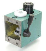
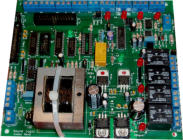
Then I decided to upgrade the electronics. Originally I had my hands full dealing with the original control box. I managed to get through the
process but thought it could be improved. Many of the cables were wired directly to the Geckos and Break out Board. I decided to do a new
control box for the machine with panel mount cable connectors.
I managed to find an industrial control enclosure on eBay for $95.00. Since it was a second hand box the top and bottom were riddled with
many holes. So I made 1/16 thick cover plates from aluminum and milled all the holes I needed on my Bridgeport. The Plexiglas front
originally had a rectangular cut out. This required a new piece of Plexiglas installed for the repair. In addition, a side plate was made to allow
the mounting of connectors. Years ago I ordered differential encoder cables from US digital. They came with non-panel mount ends. So I
needed a way to make these connectors panel mount. The solution was to tap two 4-40 holes adjacent to the rectangle cutout and use 4-40
bolts and washers top and bottom to hold the connectors from being pushed in or out when installing or removing the matching connector.
Also removed all the hardware and sanded the box then I shot some Eastwood epoxy primer on the enclosure. Now it’s time for the wiring of
the Gecko 320, limit switches etc. Part of the upgrade was removing some of the old limit switches from the machine. The machine now has
all snap action limits instead of a mix of proximity and photo sensors. All new wire and new larger cable carriers were added to the machine.
A Baldor 1 HP DC motor and variable speed controller powers the spindle. Just to be safe I ran the spindle motor cable on the outside of the
cable carrier to minimize its emi to the other cables within the cable carrier.
The motor adds a good amount of weight to the Z axis but with the servos and a
drive reduction I never see any servo faults. Something that was a concern during
the original construction. One major benefit is the spindle that runs at maximum
rpm of 5000 is very quiet when compared to a typical wood router.
Many of the control electronics were purchased from Automation Direct. They
have excellent prices on many of the parts required. The power supply was
purchased from Automation Technology a Toroidal PSU (KL-7220). My servos were
purchased from Camtronics, Dan Mauch. When selecting a servo motor it is
necessary to match its voltage requirement to the data sheet and in my case the
Gecko drives. The motor and the Geckos have a maximum allowable voltage. The new
power supply is very close to the maximum voltage for my motors. I assumed this
increase in voltage would enhance the speed of the servos. That has proven to be
true.
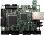
Other parts are Bob Campbell’s breakout board, Ethernet Smooth Stepper and a
c17 cnc4pc board, which monitors the servos for faults.
During original control box the grounding of the shields were an afterthought.
The new build concentrated on grounding. So far there are no strange noise
issues. The control box uses din rail power supplies and terminal blocks. It’s a very
nice system and made wiring a lot easier. There are available din rail power
supplies which I used for the upgrade. The control box is 24 x 30 inches. It ended
up being a perfect size for all the component. I like the fact that it comes with a
Plexiglas front. It’s nice to be able to check the various LEDs when the machine is running. It also forced me to do the wiring neater than the
first control box. I`m also glad I found the box used on e Bay. A new control box from this manufacturer is $500.
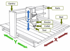
DIY CNC Build
Overall Machine Dimensions: 36 x 80
Maximum Part Size: 36 x 54
Mach 3 Software
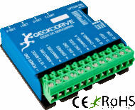
DC Brushed Servos with Gecko Drives
Thomson Round Linear Motion Assemblies
THK Linear Motion Assemblies
Spindle R8 With A Variable Speed Baldor DC Motor
Breakout Board from Bob Campbell Designs